Version
The current version available for the Lot Grading Tools is 1.0.0.0
Version Records
1.0.0.0 – Initial Release
- Minor bug fixes for release on Autodesk App Store
0.1.0.4 – Bug fix
- Fixed in an issue where if straight grading A to C, if the feature line was drawn in reverse (back of lot to front), app would throw an error and unable to obtain the highest A elevation.
0.1.0.3 – Bug fixes and Settings
- In an effort to prepare for future improvements, Lot Grader settings and Lot Labeler settings are now saved to different XML files
- Added Save/Load/Reset buttons to Lot Grader Settings dialog and the Lot Labeler dialog.
- Save allows for saving your settings out to a file at a specified location (default location initially).
- Load allows for loading up previously saved settings from a specified location.
- Reset allows for resetting back to the default settings at initial installation.
- Fixed a dialog issue with Reveal checkbox that would not allow options to become enabled again.
0.1.0.2 – Updated Support button to go to YouTube video playlist
0.1.0.1 – Initial Beta Release
PDF Help Version
Download our PDF help version using the link below
https://www.dropbox.com/s/pgtqhekcqti5qoy/How%20To%20-%20Residential%20Lot%20Grading.pdf?dl=0
Purchasing
If you like Lot Grading Tools, you may purchase Network or Standalone license(s) at the link below.
https://checkout.bluesnap.com/buynow/checkout?sku3868604=1&storeid=544367
Installation
Download the app installer from our App Installers page here:
https://redtransitconsultants.com/app-installers/
- Close Civil 3D
- Install the downloaded installer
- Open Civil 3D and locate the Lot Grading Tools ribbon tab
- For licensing, either use the initial trial license provided with purchase or submit for Standalone or Network License to the app. Both instructions show how to submit required information for a license.
Don’t hesitate to reach out to [email protected] if you need help.
Lot Grading Tool Sample File
After installing, you may access a Sample file at the path below. This will help to give an idea of what the tools expect in order to function properly and how to setup your own files to work with the tools.
C:\ProgramData\Autodesk\ApplicationPlugins\RTCL_LotGradingTools.Bundle\Contents\Win64\Lot Grading Tool Sample.dwg
LOT GRADER SETTINGS
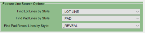
Feature Line Search Options
The Lot Grader command uses three distinct feature line
styles in order to distinguish between Lot Lines, Pad Lines, and Pad Reveal
Lines. On first run, you are only required to have Lot Lines and Pad Lines
established as Feature Lines; the Lot Grader command will generate the Pad
Reveal Lines. On subsequent selections of the same lots, the Lot Grader command
will automatically remove and replace the necessary linework on execution based
on Feature Line Style names. Select your desired three feature line styles to
use with the tool in the Feature Line Search Options.
Definition of Lettered Point Locations
Point A - Represents the front of the lot (typically where the lot line meets the Right of Way)
Point B - Represents the side swale high point
Point C - Represents the rear of the lot (typically at the terminus of the rear lot line)
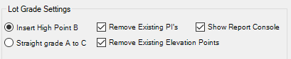
Lot Grade Settings (Side Swale Point Management and Reporting)
Use the Insert Point B option to create a high point in your side swale by adding a vertex on your side swale feature line.
Use the Straight Grade A to C option when no high point is needed.
Remove Existing PI’s will remove all existing PI’s present on the side swale feature line.
Remove Existing Elevation Points will remove all existing Elevation points on the side swale feature line
Show Report Console will display a Report console after the lot grader command is successfully completed.
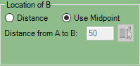
Location of B
Sets the location of the vertex that will be your side swale high point.
![]() DISTANCE - You
can specify the distance from the front of your side swale feature line (A) to
your high point (B)
DISTANCE - You
can specify the distance from the front of your side swale feature line (A) to
your high point (B)
![]() USE MIDPOINT - This
will place the side swale high point (B) at the midpoint of the side swale
feature line
USE MIDPOINT - This
will place the side swale high point (B) at the midpoint of the side swale
feature line
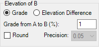
Elevation of B (Requires
Insert High Point B option to be selected)
This box allows you to set the high point elevation
![]() Grade – Set
elevation of your side swale highpoint (B) using percent slope from A to B.
Grade – Set
elevation of your side swale highpoint (B) using percent slope from A to B.
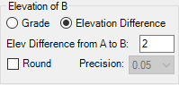
![]() Elevation
Difference – The elevation difference from the front of your feature
line (A) to the location of your high point (B)
Elevation
Difference – The elevation difference from the front of your feature
line (A) to the location of your high point (B)
Pad Elevation
This box allows you to set the Pad elevation relative to
surrounding lot line elevations
![]() Set Elevation Mode:
Set Elevation Mode:
o Highest A
– Uses the highest of the elevations at A
o Highest B
– Uses the highest of the elevations at B
o Highest C
– Uses the highest of the elevations at C
o Highest
Lot Line Elevation – Evaluate all points and use the highest of the elevations
at A, B or C
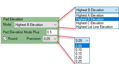
![]() Pad Elevation Mode Plus: Sets the
positive pad elevation difference with respect to the selected Elevation Mode.
Pad Elevation Mode Plus: Sets the
positive pad elevation difference with respect to the selected Elevation Mode.
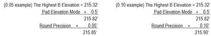
![]() If rounding is selected the Precision
sets the decimal elevation the pad will be rounded up to.
If rounding is selected the Precision
sets the decimal elevation the pad will be rounded up to.
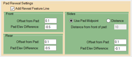
Pad Reveal
This box
allows you to add Reveal Feature Lines to the Front, Rear, and Sides of the pad.
Set the desired offset from pad and the elevation difference from the pad for
each of the front, rear, and sides options.
For the Sides,
only the Pad Midpoint or a specified distance from the front of the pad has an
established side elevation. This allows the sides to slope towards the front
and rear of the pads for drainage.
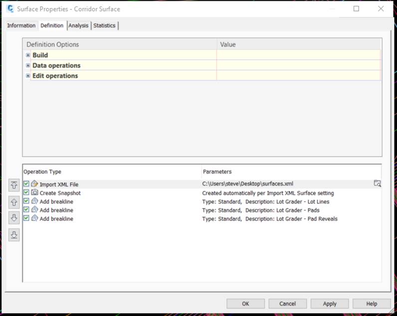
Surface Options
If
desired, you may add the Feature Lines found on the specified Lot, Pad, and Pad
Reveal Line’s assigned styles. When doing so, all Feature lines on these styles
will be added to the selected surface, which must be created prior to executing
the command. The Feature lines will be added as three distinct breakline groups, this is both for clarity in the Surface
Definition as well as for updating the surface as the Lot Grader command is
executed subsequent times. On subsequent runs, the breakline
groups are removed from the surface and then re-added so that there are always
only three distinct groups added to your surface.
Lot Labeler Settings
The Lot Labeler
command searches for Feature Lines on specified styles and extracts the
geometries of the linework to place Surface labels in the appropriate location
within a drawing referencing a specified surface. Created labels are automatically
found and removed prior to subsequent executions of the command to ensure there
are no duplicate labels generated.
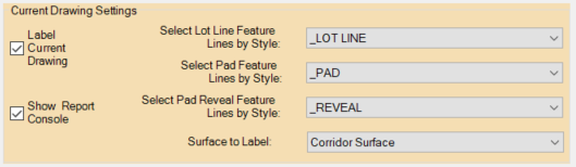
Current Drawing Settings
The Lot Labeler command uses three distinct feature line
styles in order to distinguish between Lot Lines, Pad Lines, and Pad Reveal
Lines for labeling each type according to the desired label styles selected in
the associated dialog sections. These Feature Lines must be in the current
drawing that the Lot Labeler is executed from in order for them to be found, typically
the same file utilized with the Lot Grader command.
Select if you’d like labels to appear in the current drawing and the appropriate surface you’d like the labels to reference.
Toggle on/off the report console for viewing any errors of execution.
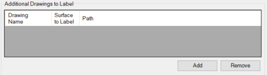
Additional Drawings to Label
If desired, add any additional drawings that you would like the Lot Labeler to label and the surface you’d like the labels to reference. This feature is great for sheet setup. Simply data reference your final surface into your sheet files, open the grading file that contains the Lot, Pad, and Reveal lines and execute the Lot Labeler adding the additional files and surface to label.
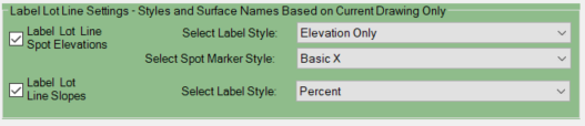
Label Lot Line Settings
Select if you’d like Spot Elevations labeled along with the Label Style and Marker Style to be utilized on the labels. This will label all PI points of the Feature Lines found on the specified Lot Line style.
Select if you’d like Two-Point Slope Labels along with the Label Style. This will label all segments between PI points of the Feature Lines found on the specified Lot Line style and will correctly draw the labels from high point to low point for each segment.
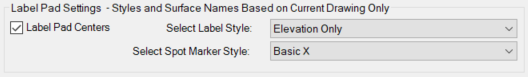
Label Pad Settings
Select if
you’d like the Pad centers to be labeled along with the Label Style and Marker
Style to be utilized on the labels. This will locate each Pad’s center point
and place a label.
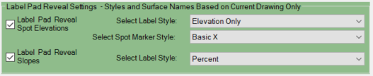
Label Pad Reveal Settings
Select if you’d
like Spot Elevations labeled along with the Label Style and Marker Style to be
utilized on the labels. This will label all PI points of the Feature Lines found
on the specified Lot Line style.
Select if you’d
like Two-Point Slope Labels along with the Label Style. This will label all segments
between PI points of the Feature Lines found on the specified Lot Line style
and will correctly draw the labels from high point to low point for each
segment.